
INSTRUMENTS > FAQ > GL7000 > KNOW-HOW ON STRAIN
KNOW-HOW ON STRAIN
TIP ON DISTORTION RELATED TO GL7-DCB FOR DATA PLATFORM GL7000 STRAIN UNIT

Data Platform GL7000 /Strain Unit GL7-DCB
1. ON STRAIN GAUGES AND STRAIN GAGE APPLIED TRANSDUCERS
Use a strain gauge to measure the strain. There are also other sensors using strain gauges.

2. PRINCIPLE OF STRAIN MEASUREMENT


About gauge method and bridge circuit
Resistance for the strain gauge increases as it stretches, and decreases as it contracts.
Yet, as the change in the gauge resistance is very small, it is measured using a Wheatstone bridge.
The figure below is a block diagram for measurments of the expansion and contraction of the object with a strain gauge.
The internal bridge of the strain unit GL7-DCB can be used to measure strain gauge 120 Ω / 350 Ω.

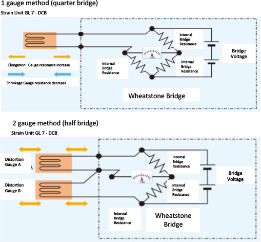

Utilizing the expansion and contraction of the measurement object, The output of 2 gauge method is double of 1 gauge method
※ Please refer to additional data (connection method and utilization), on strain gauge and bridge circuit configuration.
3. THINGS TO KNOW ABOUT STRAIN GAUGE MEASUREMENTS
About arrangement and connection of strain gauges. When constructing and measuring a bridge circuit using a strain gauge, there are 1, 2 and 4 gauge methods depending on the purpose. Depending on the purpose, placement of the strain gauge · gauge connection to the bridge circuit · output from the bridge circuit will differ.

*: Please refer to the strain gauge and bridge circuit configuration of additional document (connection method and utilization).
Various compensation methods at strain gauge measurement

Lead
Factors affecting accuracy
- Lead wire length
- Temperature change, Compensation method for factors
- Lead wire length · Temperature change
- Remote sensing * 1
Constant current drive. Auto balance
Bridge measurement
Factors affecting accuracy
- Effects other than strains to be measured (compression, tension, twist)
- Temperature change, Compensation method for factors
- Effects other than strains to be measured (compression, tension, twist)
- Change the composition (pasting method) with 2 · 4 gauge,
- Remove the distortion component you want to measure.
- Shunt calibration before starting measurement * 2
- Temperature change, Change the composition (pasting method) with 2 · 4 gauge.
- Use a self-temperature compensated strain gauge
※ 1 Remote sensing is remote sensing function eliminates conductor resistance change of cable which is an error factor. By adding 1 gauge method, 2 gauge method, 4 gauge method strain gauge measurement method and strain type transducer sensor to the remote sensing terminal by connection, the cable to the object to be measuredwill supply stable voltage excluding voltage drop due to conductor resistance.
※ 2. Shunt calibration is correct error in bridge measurement. By Built-in shunt resistance (about 60 kΩ: at 120 Ω · about 175 kΩ: 350 Ω) and by internally connecting the strain gauges in parallel and automatically correcting (calibrating), measurement is performed with improved precision with less errors in the measurement range.※ 2 Shunt calibration is Correct errors in bridge measurement. ※ 2 Shunt calibration is correct errors in bridge measurement. B
4. THINGS TO KNOW ABOUT STRAIN GAGE APPLIED TRANSDUCER MEASUREMENT
Classification and connection of vibration sensor

Reference material: Difference between common strain gauge type acceleration sensor and piezoelectric type acceleration sensor

Regarding TEDS, TEDS (Transducer Electronic Data Sheet) is a generic term for formats that describe sensor-specific information embedded in the sensor for measurement.
It is regulated in the IEEE 1451 series.
The strain unit GL 7 - DCB corresponds to the IEEE Template 1451.4 Standard Template No. 33 (strain sensor)
When TEDS compatible sensor is connected to strain unit GL 7 - DCB and TEDS information is read, stored information such as rated capacity, rated output
and unit is loaded into the strain unit GL7 - DCB. Input to the calibration value of the sensor become unnecessary, starting time for the measurement is
shortened, and can be easily performed.
* Please refer to TEDS on other document (connection method and utilization).