
GL7000 DATA PLATFORM
Main | Features | Modules | Software | Specification & Sizes | Accessories | Support & Download

GL7-DCB DC Strain Module
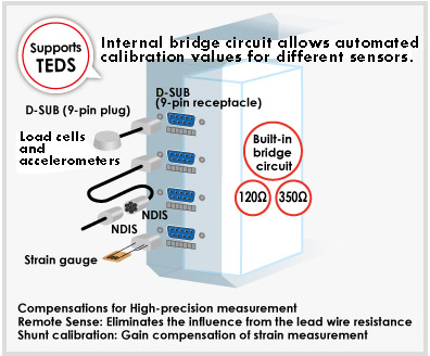
DC Strain module records data from strain gauge-based sensors including accelerometers, pressure transducer, load cells, and force meters. You can solder your sensors directly to the DSUB male connectors to measure its original voltage and resistance value. Strain module also carry its own wheat-stone bridge circuit and carries excitation power for the strain gauges and sensors allowing direct measuring inputs for the sensors.
Filter function
High accuracy can be achieved using various filters such as low-pass and anti-aliasing filters.

Application Examples
GL7-DCB Specification
| Item | Description | |
|---|---|---|
| Type of module | DC bridge amplifier module - for strain gauge or sensor based on a strain gauge - | |
| Model number | GL7-DCB | |
| Number of input channels | 4 channels | |
| Input method | All channels isolated balanced input, Simultaneous sampling, D-SUB type connector (9 pins, receptacle) |
|
| Sampling speed (interval) | 100 k Samples/s to 1 Sample/h (10 μs to 1 hr.) | |
| Built in RAM | 2 million samples for each channel | |
| Input type | Strain, Voltage, Resistance value (including potentiometer) | |
| Measurement range | Strain | 500, 1000, 2000, 5000, 10000, 20000 με (με: 10-6 strain) 0.2, 0.25, 0.4, 0.5, 1, 2, 2.5, 4, 5, 10 mV/V * Available ranges vary by the excitation voltage for the bridge. |
| Voltage | 1, 2, 5, 10, 20, 50, 100, 200, 500 mV, 1, 2, 5 V Full Scale | |
| Resistance | 1, 2, 5, 10, 20, 50, 100, 200, 500 Ω, 1, 2, 5, 10, 20, 50 kΩ Full Scale | |
| Measurement accuracy (*1) | Strain | ±(0.2% of Full Scale + 10 με) |
| Voltage | ±(0.2% of Full Scale + 10 μV) | |
| Resistance | ±0.5% of Full Scale | |
| A/D converter | Successive Approximation type, 16 bits (effective resolution: 1/40000 of the measuring full range) | |
| Input impedance | 10 MΩ ±5% | |
| Gauge ratio | 2.0 constant | |
| Supported sensor | Strain (*2) | Strain gauge Quarter bridge (single gauge) in 2-, 3- or 4-wire (supports remote sensing in 3- or 4-wire) Half bridge (dual gauge) in 3-, 4-, 5-wire (supports remote sensing in 4- or 5-wire) Full bridge (quad gauge) in 4- or 6-wire (supports remote sensing in 6-wire) |
| Transducer/sensor based on a strain gauge Full bridge type in 4-wire, Full bridge type in 6-wire (supports remote sensing) |
||
| Resistance | Resistor, Potentiometer | |
| Bridge resistance | 50 Ω to 10 kΩ * Available excitation power varies by selection of element. | |
| Built-in element of the bridge | 120 or 350 Ω for the quarter- and half-bridge * Available excitation power varies by selection of element. |
|
| Excitation power | Voltage mode | 1, 2, 2.5, 5, 10 V DC * Excitation voltage 5 and 10 V is available when bridge resistance is the 350 Ω or higher. |
| Current mode | Constant current: 0.1 to 20 mA (supported voltage is up to 10 V.) | |
| Zero Adjust for Strain gauge | Method | Fully automatic (via push button or setting the condition menu) |
| Max. Range | ±10,000με (με:10-6 Strain) | |
| Remote sensing | 3- or 4-wire in quarter bridge, 4- or 5-wire in half bridge, 6-wire full bridge | |
| Shunt Calibration | Approx. 60 kΩ (120 Ω gauge), Approx. 175 kΩ (350 Ω gauge) | |
| Maximum input voltage | Between (+) / (-) terminal | 10 V, Common-mode voltage: 10 Vrms AC |
| Between channels ((-) terminals) | 10 Vp-p | |
| Between channel / GND | 60 Vp-p | |
| Max. voltage (withstand) | Between channels | 1000 Vp-p (1 minute) |
| Between channel / GND | 1000 Vp-p (1 minute) | |
| Isolation | Between channel / GND | Min. 100 MΩ (at 500 V DC) |
| Common-mode rejection ratio | Min. 80 dB (50/60 Hz, Signal source impedance: Max. 300 Ω) | |
| Frequency response | DC to 20 kHz | |
| Filter | Low pass | Off, Line (1.5 Hz), 3, 6, 10, 30, 50, 60, 100, 300, 500 Hz, 1k, 3k, 5k, 10k Hz (in -30dB/oct) |
| Anti-aliasing | Off, On | |
| Support TEDS | Standard | IEEE 1451.4 Class2 (Temperate No.33) |
| Support | Reading information from the sensor and setting it to module | |
| External dimensions (W x D x H) | Approx. 49 x 136 x 160mm (Excluding Protection) | |
| Weight | Approx. 840 g | |
Subject to the following conditions:
Room temperature is 23ºC ±5ºC.
When 30 minutes or more have elapsed after power has been turned on.
Filter is set to 10 or Line.
Sampling rate is set to 1 second.
GND terminal is connected to ground.
*2 Remote sensing is not available when an NDIS connector is used.
● When a bridge box is used, the connection needs to be 4-wire or 6-wire full bridge. When connecting with a Half bridge (Opposite side), an additional bridge box is required.
● Bridge excitation: Constant current drives a strain gauge type sensor or a 4-wire full bridge.
● Shunt calibration is available only when the connection uses a 3-wire, 4-wire quarter bridge, 5-wire full bridge, or 6-wire full bridge.