

GRAPHTEC LEGACY PRODUCTS
Western Graphtec developed premier linear chart recorders, pen oscillographs, and thermal array coders that provided paper records for electronic signals in both data acquisition and signal analysis. Graphtec’s legacy chart recorders were considered leading recorders that carried paper options for oscilloscopes carrying 0Hz to 10Khz signals. Application varied from sound, vibration, phase shifts, velocity, acceleration, brain waves, magnetic force, and even animal heart beats.
Carrying military-grade precision and performance that matched leading electronic testing products of the day, Graphtec’s WR linear chart recorders and WX X-Y recorders have proven to offer the data that industry professionals trust day in and day out. Many of these products are still being used fully in line in aerospace, medical, and military applications. Some are used to secure your next flight with strain testing for airplane wings. Others are used to secure the smoothness of the catheter that goes into your body.
The strength of the precision and the guiding principals behind Western Graphtec can still be seen in the new line-up of dataloggers and data acquisition platforms that carries our company to this day. Key elements of that principals are:
Channel to Channel Isolation for accurate trust-worthy data for multi-channel applications.
Precision High Speed Dynamic Signal Recording
Easy to access Data Records
Simultaneous and Real Time display and Storage
Click >> to download Western Graphtec Legacy Note in pdf (131 KB)
LEGACY MODELS
GL840 | GL240 | GL220 | GL200 | GL200A
GL1100 | GL1000 | GL900 | GL820 | GL800 | GL500/500A | GL400/450
MT100 | WR300/WR310 | WR3320A | WR7700 | WR8000 | WR9000 | WR1000
Support Period for Legacy Models in pdf (83 KB) >> Download Now
MT100

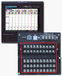
Graphtec’s multi input paperless data recorder includes modern conveniences such as Ethernet and USB interfaces, plus a USB flash memory port, so you can easily get the data out of your MT100 and transfer it to your computer. Data are normally captured into the GL’s large internal memory, at rates selectable from 100 ms to 1/hour! You can record for hours, days, or even weeks with the 12 MS memory.
An isolated input system has been implemented to enable worry-free measurement. Ten input channels have been provided to meet multichannel needs.
EASY-TO-VIEW, EASY-TO-USE PAPERLESS RECORDER:
Dust proof, drip proof, vibration proof for use at harsh environment
Analog recorder chart paper image for easy-to-read waveform display
Compact design 144(W) x 144(H) x 200(D) mm
MAIN FEATURES:
The MT100 has a built-in 5.7" TFT color LCD display
Built-in Ethernet and USB 2.0 interfaces
Weight of 2.1kg and dimensions (144mm x 144mm x 200mm)
Direct recording to USB memory stick
12MB Built-in Non-volatile memory retains data even after the MT100 is turned off
Voltage (20mV to 50V ), Temp Thermo-couplers (K, E, J, T, N, R, S, T, B, W) and Humidity
Up to 200 Multi-function PhotoMOS relay isolated input channels
16-bit A/D converters (14-bit processing)
Max Sample rate of 10 Samples/second
Statistical analysis functions
10-ISOLATED CHANNELS AND MULTIFUNCTION INPUT TO ACCOMMODATE VARIOUS MEASUREMENT NEEDS
An isolated input system has been implemented to enable worry-free measurement. Ten input channels have been provided to meet multichannel needs.
ABUNDANT SELECTION OF INPUT TYPES TO MEET DIVERSE MEASUREMENT NEEDS
REAR PANEL TERMINAL BLOCK
M4 screw terminals have been used for the input terminals to simplify wiring. The terminals can be tightened easily with a screwdriver. If an abnormal value arises, the alarm function informs the operator of the abnormality. Alarm output terminals for four channels are provided as standard.
2-TYPES OF HUMIDITY MEASUREMENT ARE ENABLED
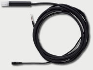
USING THE DEDICATED HUMIDITY SENSOR (B-530)
DIRECT CONNECTION OF DRY-BULB AND WET-BULB SENSORS
Humidity measurement can be performed by connecting the dedicated humidity sensor to an analog terminal on the MT100 unit.
Operating temperature range:-25°C to +80°C
Operating humidity range:0% RH to 100% RH.
Relative humidity measurement precision:±3% RH (5% RH to 98% RH at 25°C)
External dimensions:Φ14 mm x 80 mm (excluding the cable)
Cable length:3 m
LARGE VOLUMES OF DATA CAN BE DIRECTLY CAPTURED TO
A USB MEMORY STICK OVER A LONG PERIOD OF TIME
A USB memory stick is used for the recording medium. A large volume of data measured over a long period of time on the ten available channels can be directly written to and stored on the memory stick. The MT100’s internal memory consists of 14-MB flash media.
DATA CAPTURE TIME (WHEN MEASUREMENT IS PERFORMED ON 10-CHANNELS)
| Capture interval (sampling speed) | 100ms | 1s | 10s | 1min |
|---|---|---|---|---|
| 14-Mbyte internal flash memory | Approx. 13 hours | Approx. 5 days | Approx. 53 days | Approx. 323 days |
| USB memory stick (256 Mbytes) | Approx. 9 days | Approx. 98 days | Approx. 987 days | Approx. 5,925 days |

USB MEMORY STICK REPLACEABLE EVEN DURING MEASUREMENT
The USB memory stick can be removed* even while long-term recording is being performed to enable checking of measurement that is still in progress. If the USB memory stick is removed, data capture is switched to the MT100’s internal buffer memory for a period of approximately 10 minutes. When the USB memory stick is reinserted in the MT100, data is once again captured to the memory stick.
* Key operation is required at the time of USB memory stick removal.
DUSTPROOF, MOISTURE-PROOF, VIBRATION-RESISTANT STRUCTURE FOR SEVERE MEASUREMENT ENVIRONMENTS; SPACE-SAVING DESIGN
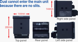
In order to withstand severe field environments, the structure has been designed to be dustproof, moisture-proof, and vibration-resistant. The front panel of the MT100 unit is an IP65-compliant structure that is both dustproof and moisture-proof. To prevent the penetration of dust, there are no slits in the MT100 unit itself. In addition, the unit’s vibration-resistant structure complies with the Vibration Testing Methods for Automobile Parts Standard, Type 1 Class A.
The front panel’s dustproof and moisture-proof structure complies with IP65 protection standards.
The vibration-resistant structure complies with the [Vibration Testing Methods for Automobile Parts Standard, Type 1 Class A].
Moreover, the space-saving design offers a reduced depth of only 200 mm to enable easy installation in various types of test systems.
EASY-TO-VIEW WAVEFORM DISPLAYS PRESENTED AS IF ON CHART PAPER USED BY ANALOG RECORDERS
A large-format 5.7-inch color TFT liquid crystal display, bright and easy to read, is built-in. The measurement results are faithfully reproduced in the display formats used by conventional analog recorders. Waveform displays that are similar to those of pen recorders or dot-printing recorders enable the measurement progress to be easily ascertained at a glance. Four display formats are provided to enable the most easy-to-view format to be selected for each measurement application.
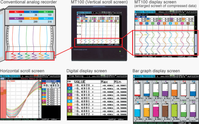
A compressed display of the time axis is provided at the bottom of the screen. As with a pen recorder or a dot-printing recorder, the waveform display enables the measurement progress to be easily ascertained at a glance. The compression ratio can be set in ten increments within the 1/10 to 1/100 TIME/DIV range.
COMPREHENSIVE NETWORK FUNCTIONS
A diverse range of network functions can be used to suit the measurement application.
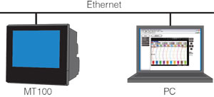
Waveform display and MT100 settings can be made via a web browser such as Internet Explorer.
Data stored in the MT100’s internal memory or the USB memory stick can be transferred or deleted through operations performed at the computer.

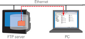
The data captured to the MT100’s internal memory or the USB memory stick can be automatically backed up to the FTP server at fixed intervals.

The MT100’s time can be synchronized to the NTP server’s time at periodic intervals.
(NTP : Network Time Protocol)
MT100 APPLICATION SOFTWARE
The application software provided as a standard accessory with the MT100 enables easy online measurement and conversion of the data file format.
CONVENIENT FUNCTIONS:
Statistical calculation/Alarm history
Password protection function
Batch conversion of the captured data to CSV format
Search function for specific points in the captured data
Direct to Excel function
Channel group function
Comment input function
MAIN SCREEN (Y-T)

CONVENIENT FUNCTIONS

EASY SETTING
Icon keys have been provided for intuitive waveform operations. The number of setting screens has been reduced to only six. Settings in the amp setting screen and other screens can be performed while viewing the input signals.
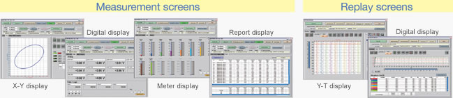
VARIOUS SCREEN DISPLAYS
Y-T, X-Y, Digital display, Meter display, and Report display screens have been provided to suit various measurement applications. In addition, the Replay display screen can be specified as Y-T, X-Y between cursors or Digital display.
MAIN UNIT SPECIFICATIONS
| Item | Description | |||
|---|---|---|---|---|
| Number of analog input channels | 10 channels | |||
| External Input/Output | Trigger input, Logic input 4 ch or Pulse input 4 ch, Alarm output 4 ch | |||
| Sampling interval | 100 ms to 1 h (Max:100 ms/10ch) | |||
| TIME/DIV | 1 sec/DIV to 72 h/DIV | |||
| Trigger function | Type | Start | Data capture starts when a trigger is generated | |
| Stop | Data capture starts when a trigger is generated | |||
| Condition | Start | Off, Level, Alarm, Scheduled time, External, Day | ||
| Stop | Off, Level, Alarm, Scheduled time, Time, Day, External | |||
| Condition | Analog | H, L, Window In, Window Out, Rate of change | ||
| Logic | H, L | |||
| Pulse | H, L, Window In, Window Out, Rate of change | |||
| Alarm output | No. of channels | 4 | ||
| Output format | Relay contact output (NO/NC) | |||
| Output conditions | Level judgement, Window judgement, Logic pattern judgement, Pulse judgement | |||
| Output terminal | M4 screw terminal | |||
| Rating | 250 VAC/2A, 30 VDC/2A | |||
| Pulse input range | Count mode | 50, 500, 5000, 50 k, 500 k, 5 M, 50 M, 500 M C/F.S. (max. 50 k/sampling interval) | ||
| Inst. Mode | 50, 500, 5000, 50 k, 500 k, 5 M, 50 M, 500 M C/F.S. (max. 50 k/sampling interval) | |||
| RPM mode | 50, 500, 5000, 50 k, 500 k, 5 M, 50 M, 500 M RPM/F.S. (max. 50 k/sec) | |||
| Calculation function | Statistics calculation *1 | Average, Peak, maximum, Minimum, RMS (2 calculations can be set simultaneously) | ||
| Calculation between channels | Addition, Subtraction, Multiplication, Division (for analog input ch1 to ch10) | |||
| Wet-and dry-bulb temperature conversion | Humidity is calculated from the measured temperature of Wet-bulb and Dry-bulb (Dry bulb : fixed to ch1, Wet bulb : fixed to ch2, Range 0 to 100 %) |
|||
| Other function | Searching, Annotation input, Message, Marker function | |||
| Interface to PC | Ethernet (10BASE-T / 100BASE-TX), USB (Compatible with full speed) | |||
| Ethernet function | Web server function, FTP server function, FTP client function, NTP client function | |||
| USB function | USB drive mode (File transfer/delete of internal memory) | |||
| Internal storage device | Internal flash memory : 14 Mbyte, USB memory slot (compatible with full speed) *2 | |||
| Display | Size | 5.7 inch TFT color LCD | ||
| Displayed items | Waveforms + Digital values (vertical, horizontal), Digital + Calculation, Bar graph (vertical) | |||
| Clock accuracy (23°C environment) | ±0.002 % (within approx. 50 sec per month) | |||
| Operating environment | Temperature : 0 to 50 °C, Humidity : 5 to 85 % R.H. | |||
| Withstand voltage | Between each input channel and GND: 1 minute at 350 Vp-p | |||
| Between input terminals: 1 minute at 350 Vp-p | ||||
| Power supply | 100 to 240 V AC / 50 to 60 Hz, M4 screw terminal (Power cord is not attached) | |||
| Power consumption | 38 VA (when LCD is ON) | |||
| External dimensions (W x H x D)(approx.) | 144 mm x 144 mm x 200 mm | |||
| Weight (approx.) | 2.1 kg | |||
| Vibration resistance | Compatible with JIS Vibration testing methods for automobile Type 1 Class A-equivalent | |||
| Dust proof, Drip proof: IP65 compatible (for front panel only) | ||||
ANALOG INPUT SPECIFICATIONS
| Item | Description | |||
|---|---|---|---|---|
| Type of input terminal | M4 screw type terminal | |||
| Measurement range | Voltage | 20, 50, 100, 200, 500 mV, 1, 2, 5, 10, 20, 50, V, 1-5 V F.S. | ||
| Temperature | Thermocouple : K, J, E, T, R, S, B, N, W (WRe5-26) | |||
| R.T.D. : Pt100, JPt100, Pt1000 (IEC751) | ||||
| Humidity | 0 to 100 % RH (Voltage 0 to 1 V conversion, when using optional B-530 humidity sensor is used) | |||
| Input filter | Off, 2, 5, 10, 20, 40 (Moving average) | |||
| Measurement accuracy *3 | Voltage | ±0.1 % of F.S. | ||
| Thermocouple | Measurement range | Accuracy | ||
| R/S | 0 TS 100 °C 100 < TS 300 °C R : 300 < TS 1600 °C S : 300 < TS 1760 °C |
± 5.2 °C ± 3.0 °C ± (0.05 % of rdg + 2.0 °C) ± (0.05 % of rdg + 2.0 °C) |
||
| B | 400 TS 600 °C 600 < TS 1820 °C |
± 3.5 °C ± (0.05 % of rdg + 2.0 °C) |
||
| K | -200 TS -100 °C -100 < TS 1370 °C |
|||
| E | -200 TS -100 °C -100 < TS 800 °C |
|||
| T | -200 TS -100 °C -100 < TS 400 °C |
|||
| J | -200 TS -100 °C -100 < TS 100 °C 100 < TS 1100 °C |
|||
| N | 0 TS 1300 °C | |||
| W | 0 TS 2000 °C | |||
| R.T.D. | Pt100 | -200 to 850 °C (FS = 1050 °C) | ||
| JPt100 | -200 to 500 °C (FS = 700 °C) | |||
| Pt1000 | -200 to 500 °C (FS = 700 °C) | |||
| * If the reference junction compensation is internal, add ± 0.5 °C to each of the above values. | ||||
| A/D converter | 16 bit (out of which 14 are internally acknowledged) | |||
| Input resistance | 1MΩ ±5% | |||
| Allowable signal source resistance | Up to 300Ω | |||
| Maximum input voltage | 60 Vp-p (Between ± terminals) | |||
| 60 Vp-p (Between input terminals) | ||||
| 60 Vp-p (Between input terminal and GND) | ||||
| Withstand voltage | Between each input channel and GND: 1 minute at 350 Vp-p | |||
| Between input terminals: 1 minute at 350 Vp-p | ||||
Remarks: *1. for realtime and between cursors (when data reviewing). *2. 1 file 2 GB (it depends on used USB memory). *3. Thermocouple: 0.32φ for T type, 0.65φ for other types
PC SOFTWARE SPECIFICATIONS
| Item | Description |
|---|---|
| Compatible OS | Windows 2000/XP/Vista (32 bit and 64 bit version) |
| Function | Control of main unit, Realtime data capture, File conversion |
| Max. number of controlable units | 10 units |
| Max. number of controlable channels | 100 channels |
| Settable items | AMP settings, Capture settings, Trigger/Alarm settings, Report settings, Other |
| Captured data | Realtime data, Internal memory data, USB memory data (CSV and Binary data) |
| Display | Analog waveforms, Logic waveforms, Pulse waveforms, Digital values |
| File conversion | Data conversion between cursors/All data |
| Monitor functions | Alarm monitor enables sending of email to the specified address |
| Dual display function | Current/previous data display |
| Statistics calculation, report | Maximum, minimum, average data during measurement |
| Report function | Automatic creation of daily or monthly files |
ACCESSORIES
| Item | Model | Remark |
|---|---|---|
| Humidity sensor | B-530 | Cable length : 3 m |
| Rod-shaped thermocouple K type | RIC-410 | Cable length : 1.1 m |
| Thermocouple K type for static surface | RIC-420 | Cable length : 1.1 m |
| L-shaped thermocouple K type for static surface | RIC-430 | Cable length : 1.1 m |
MANUAL & BROCHURE / SPEC SHEET
User Manual MT100 in pdf (6.2 MB) >> Download Now
Brochure / Spec Data Sheet MT100 in pdf (555 KB) >> Download Now
Warranty Registration Online >> Click Here
USB DRIVER
For Windows Vista, 7, 8, 8.1, and 10 (x32 and x64) V 2.03 (1.9 MB) >> Download Now
SOFTWARE
Software V1.06 for Windows 10, Vista, 8.1, 8, 7 (x32 and x64) (66 MB) >> Download Now
WR300 / WR310 SERIES
ARRAY-CORDERS MEMORY RECORDER

The WR310 Series Thermal Arraycorders are economical waveform recorders available in 4, 8 and 16 channel configurations. Unlike old-fashioned paper-only recorders, the WR310 series is a 21st century technology through and through.
Available are convenient 2-channel plug-in modules that adapt the WR300 to a wide variety of input types and sensors, including voltages up to 500 V, strain gages, thermocouples, frequency/RPM signals, and more. There’s also a logic input amp which offers the same number of inputs as the base machine (4, 8, or 16).
Capture data to memory, to the paper, or to the optional hard drive* or PCM-CIA flash RAM memory card. Data are shown all the time of the 8.4″ color LCD screen in a variety of formats, including scroll. oscilloscope, XY, and even FFT! Data can be printed in real time or after acquisition, to the built-in 100 or 200 mm wide chart output.*
Ethernet and USB interfaces are built-in so that you can control the system from your computer (OPS software is included). The same software and interfaces can also transfer data to your computer and convert it to several popular formats, including Excel and delimited ASCII.
WR300 16-channel unit left side – showing 8 WR3 series 2-channel input amps plugged in, plus 4 x 4-ch logic amps (round connectors below)
VARIOUS CHART TYPES AND SIZES ARE SUPPORTED
WR300 8 or 16-ch unit with the optional Z-fold paper take-up capability
EASY OPERATION - INTUITIVE CONTROLS
A separate bank of chart speed setting keys enables you to change the chart speed at any time, and four directional cursor keys are provided for easy menu selection. The additional buttons of the WR310 makes this unit even easier to use than similar products.
WIDE FORMAT PRINTING*
The wide 200 mm (8 inch) paper allows data to be printed with ultimate clarity and precision – even better than what can be shown on the built-in LCD display.
DATA UPLOAD TO YOUR PC
OPS023 control/transfer/conversion software is included, so you can convert data captured to Excel™ or delimited ASCII format. Need more analysis power? FlexPro™ can open Graphtec data files natively, providing a powerhouse analytical capabilities with an Excel-like interface
Excel is a registered trademark of Microsoft Corporation
FlexPro is a trademark of Weisang GMBH
MAIN FEATURES
Models available with 4, 8 or 16 input channels
8.4″ color LCD monitor for data display and the graphical user interface
Plug-in 2-channel WR3 series amplifiers adapt the system to a wide variety of input types and sensors.
Up to 1 MS/s sampling rate on all channels
Bandwidth (frequency response): dc to 50 kHz
1 MSample internal memory PER CHANNEL is standard
Built-in 200mm (8″) wide thermal array printer in the 8- and 16-ch models; 100 mm wide printer in the 4-ch model
Interfaces: Ethernet, USB, and slot for flash memory cards
Performance, reliability and ease of use Includes PC software for control, data transfer and conversion to popular formats
OPTIONS & UPGRADES
WR3 series plug-in modules (2-ch each)
40 GB internal HDD*
Flash memory cards for the PCM-CIA drive
4-, 8-, or 16-channel logic input module
IRIG time code interface option*
DC power option in lieu of 120/240 VAC 50/60 Hz
* WR310 series 8 and 16 channel models are available with the IRIG and 40 GB hard drive (HDD) options. WR300 series models are not compatible with these options. the WR300-4 four channel model has a 100mm wide chart instead of 200mm wide chart.
BROCHURE & DOWNLOAD
WR300 Series Brochure / Spec Sheet (7.9 MB) >> Download Now
WR300 User Manual in pdf (2.6 MB) >> Download Now
USB Driver V2.03 (1.9 MB) >> Download Now
Software V1.01 APS for Windows Vista, 8.1, 8, 7 (x32 and x64) (72 MB) >> Download Now
Firmware V3.13 for Windows 10, Vista, 8.1, 8, 7 (for V3.12 or later) (2 MB) >> Download Now
WR3320A
LINEARCORDER

The WR3320A Linearcorder Mark VII is a thermal writing pen oscillograph which has been designed to meet the standards required by even the most exacting of professionals, including government agencies all over the world. This is a proud testament to their reliability and legendary performance.
WR7700
ARRAY-CORDER
DOWNLOAD
WR7700 Software (668 KB) >> Download Now
Control and Data Transfer Program – connects via RS232 only. Does not allow any on-line visualization of waveforms. A handy setup utility which allows unlimited setups, easy text entry, and data transfer/conversion to ASCII.
WR8000
ARRAY-CORDER
DOWNLOAD
WR8000 Software V1.02 (689 KB) >> Download Now
Control and Data Transfer Program – connects via RS232 only. Does not allow any on-line visualization of waveforms. A handy setup utility which allows unlimited setups, easy text entry, and data transfer/conversion to ASCII.
WR9000
ARRAY-CORDER
WR1000
ARRAY-CORDER
GL1100 / GL1000
DATA PLATFORMS
GL900
BROCHURE & DOWNLOAD
User Manual GL900 in pdf (8.6 MB) >> Download Now
Brochure / Spec Data Sheet GL900 in pdf (4.6 MB) >> Download Now
Graphtec 3-Yr Standard Warranty on main unit in pdf (Effective Aug.1, 2018) >> Download Now
Warranty Registration Online >> Click Here
Graphtec Product Line-Up Catalog in pdf (13.3 MB) >> Download Now
For Windows Vista, 7, 8, 8.1, and 10 (x32 and x64) V 2.03 (1.9 MB) >> Download Now
GL Connection Software V2.20 for Windows Vista - 10 Updated 10/31/18 (45.2 MB) >> Download Now
GL Connection Software V2.20 Release Note in pdf (99 KB) >> Download Now
Software V1.04 for Windows Vista (x32 and x64) (61 MB) >> Download Now
GL820
BROCHURE & DOWNLOAD
GL820 Brochure Data Sheet in pdf (1.4 MB) >> Download Now
GL820 User Manual V1.51 in pdf (11.7 MB) >> Download Now
GL820 Application Software User Manual V1.51 APS in pdf (7.6 MB) >> Download Now
GL820 GL Connection User Manual V1.51 APS in pdf (3.4 MB) >> Download Now
GL Connection Software V2.20 for Windows Vista - 10 Updated 10/31/18 (45.2 MB) >> Download Now
GL Connection Software V2.20 Release Note in pdf (99 KB) >> Download Now
GL820 Software V1.80 (15.6 MB) >> Download Now
The GL-Connection application software is software used to perform USB and LAN connections with the GL, to configure GL settings, and to carry out data recording, data playback and real-time display of input signals.
Compatibility: Windows Vista – 10
GL820 Software V1.80 Release Note in pdf (94 KB) >> Download Now
GL820 Software V1.12 (69 MB) >> Download Now
The GL-Connection application software is software used to perform USB and LAN connections with the GL, to configure GL settings, and to carry out data recording, data playback and real-time display of input signals.
Compatibility: Windows Vista – 8.1
GL800
BROCHURE & DOWNLOAD
GL800 User Manual V1.52 in pdf (6.3 MB) >> Download Now
GL800 Quick Start Guide in pdf (2 MB) >> Download Now
GL800 Spec Sheet in pdf (839 KB) >> Download Now
GL800 Firmware V2.20 (1.8 MB) >> Download Now
GL800 Software APR V1.04 (72 MB) >> Download Now
Control and Data Transfer Program – connects via either Ethernet or USB 2.0. Allows on-line visualization of recorded data. Allows transfer of data from the instrument to your computer, and the conversion of data files from Graphtec binary files to ASCII text or Excel formats.
Windows 2000 – 7
GL800 USB Driver V2.03(1.9 MB) >> Download Now
USB Driver for Windows Vista – 8
GL500 / GL500A
BROCHURE & DOWNLOAD
GL500 User Manual in pdf (3.7 MB) >> Download Now
GL500A User Manual in pdf (8.6 MB) >> Download Now
GL500A Application Manual in pdf (2.2 MB) >> Download Now
GL500 Software (23 MB) >> Download Now
Control and Data Transfer Program – connects via either Ethernet or USB 2.0. Allows on-line visualization of recorded data. Allows transfer of data from the instrument to your computer, and the conversion of data files from Graphtec binary files to ASCII text or Excel formats.
Windows 2000, XP, Vista
GL400 / GL450
GL220
BROCHURE & DOWNLOAD
GL220 Brochure and Data Sheet in pdf (1.3 MB) >> Download Now
GL220 User Manual in pdf (7.6 MB) >> Download Now
GL220 GL Connection User Manual in pdf (3.4 MB) >> Download Now
GL220 Application Software User Manual in pdf (7.6 MB) >> Download Now
GL Connection Software V2.20 for Windows Vista - 10 Updated 10/31/18 (45.2 MB) >> Download Now
GL Connection Software V2.20 Release Note in pdf (99 KB) >> Download Now
GL220 Software V1.80 (15.6 MB) >> Download Now
The GL-Connection application software is software used to perform USB and LAN connections with the GL, to configure GL settings, and to carry out data recording, data playback and real-time display of input signals.
Compatibility: Windows Vista – 10
GL220 Release Note V1.80 in pdf (94 KB) >> Download Now
GL220 Software APS V1.12 (69 MB) >> Download Now
The GL-Connection application software is software used to perform USB and LAN connections with the GL, to configure GL settings, and to carry out data recording, data playback and real-time display of input signals.
Compatibility: Windows Vista – 8.1
GL200
BROCHURE & DOWNLOAD
GL200 Data Sheet in pdf (706 KB) >> Download Now
GL200 Input Unit Specifications in pdf (51 KB) >> Download Now
GL200 Software APS V1.40 (68.4 MB) >> Download Now
Control and Data Transfer Program – connects via either Ethernet or USB 2.0. Allows on-line visualization of recorded data. Allows transfer of data from the instrument to your computer, and the conversion of data files from Graphtec binary files to ASCII text or Excel formats.
Windows 2000 – Vista
GL200A
BROCHURE & DOWNLOAD
GL200A User Manual in pdf (4.5 MB) >> Download Now
GL200A Quickstart Guide in pdf (2.5 MB) >> Download Now
GL200A Software APS V1.40 (71.6 MB) >> Download Now
Control and Data Transfer Program – connects via either Ethernet or USB 2.0. Allows on-line visualization of recorded data. Allows transfer of data from the instrument to your computer, and the conversion of data files from Graphtec binary files to ASCII text or Excel formats.
Windows 2000 – 7
